 English
 Chinese
Electric Double Layer Capacitors (EDLCs), also known as supercapacitors or ultracapacitors, are energy storage devices that bridge the gap between traditional capacitors and batteries. They store energy by means of the electrical double layer phenomenon, which occurs at the interface between a solid electrode and an electrolyte solution.
Here’s how they work:
Electrical Double Layer: When a solid electrode (usually made of activated carbon or another porous material) is immersed in an electrolyte solution, an electrical double layer forms at the electrode-electrolyte interface. This double layer consists of two layers: the inner layer contains adsorbed ions of opposite charge to the electrode, and the outer layer contains counterions in the electrolyte. This separation of charges forms a capacitance, similar to the plates of a capacitor.
High Surface Area: The key to EDLCs’ high capacitance is the high surface area of the electrode material. The porous structure provides a large area for ions to be stored, leading to a higher charge storage capacity compared to traditional capacitors.
Fast Charging and Discharging: Unlike batteries, EDLCs can be charged and discharged very rapidly due to the absence of chemical reactions. This makes them suitable for applications requiring frequent energy bursts or quick power delivery.
Long Cycle Life: EDLCs typically have a longer cycle life compared to batteries. They can endure hundreds of thousands of charge-discharge cycles without significant degradation.
Low Energy Density, High Power Density: While EDLCs have high power density (ability to deliver high power quickly), they generally have lower energy density (amount of energy stored per unit mass) compared to batteries. This makes them more suitable for applications where rapid energy bursts are required.
Complementary to Batteries: EDLCs are often used in conjunction with batteries to address their limitations. Batteries provide higher energy density and slower energy release, while EDLCs provide quick bursts of power and help manage load fluctuations.
Applications of EDLCs include:
- Regenerative Braking: In hybrid and electric vehicles, EDLCs can capture and store energy during braking events and release it during acceleration, improving energy efficiency.
- Backup Power: They can serve as backup power sources in electronics, ensuring a reliable power supply during power outages or sudden voltage drops.
- Pulse Power Applications: EDLCs are used in applications requiring high power pulses, such as camera flashes, wireless sensor networks, and defibrillators.
- Renewable Energy: They can smooth out fluctuations in renewable energy sources like solar and wind, improving grid stability.
- Industrial and Grid Applications: EDLCs can be used in industrial settings for load leveling, where they help manage and stabilize peak power demands.
In summary, Electric Double Layer Capacitors are energy storage devices that utilize the electrical double layer phenomenon to store energy on the surface of a porous electrode. They offer rapid charge and discharge capabilities, long cycle life, and high power density, making them valuable in various applications alongside traditional batteries.
The construction and principle of an Electric Double Layer Capacitor (EDLC), also known as a supercapacitor or ultracapacitor, involve creating a large surface area for the formation of an electrical double layer at the electrode-electrolyte interface. This double layer stores electrical energy through the separation of charges and doesn’t involve chemical reactions like batteries. Here’s a breakdown of the construction and principle:
Construction:
Electrodes: EDLCs have two electrodes made of a porous material with a very high surface area. This material is often activated carbon or a similar material with a structure that provides a large number of tiny pores and crevices. The high surface area allows for a greater amount of ions to be stored on the electrode.
Separator: A separator is placed between the two electrodes to prevent direct contact, which could cause a short circuit. The separator is typically a porous material that allows ions to pass through but not the movement of larger particles.
Electrolyte: An electrolyte is a conductive solution that fills the space between the electrodes. It consists of ions, which are electrically charged particles. When the electrodes are immersed in the electrolyte, the ions can move freely within it.
Current Collectors: Current collectors are conductive materials that provide the connection between the electrodes and the external circuit. They ensure that the stored energy can be easily transferred to and from the device.
Principle:
Formation of Double Layer: When the electrodes are immersed in the electrolyte, a separation of charges occurs at the interface between the electrode and the electrolyte. This is called the electrical double layer. The porous structure of the electrode material provides a large surface area where ions from the electrolyte can adsorb (stick) onto the electrode surface.
Adsorption and Desorption: The ions in the electrolyte are attracted to the electrode’s surface due to the electric potential created by the charge separation. Positively charged ions (cations) are attracted to the negatively charged electrode, and negatively charged ions (anions) are attracted to the positively charged electrode. This process is reversible – ions can be adsorbed onto the electrode surface when charging and desorbed when discharging.
Capacitive Behavior: The separation of charges at the electrode-electrolyte interface creates a capacitance-like behavior. The electrical double layer functions like the dielectric material in a traditional capacitor, and the charge separation creates a voltage difference between the electrodes.
Energy Storage: The amount of energy stored in an EDLC is proportional to the surface area of the electrodes and the square of the voltage across them. As the voltage increases, more charges can be stored in the electrical double layer, increasing the energy storage capacity.
Charge and Discharge: During charging, energy is stored as ions accumulate at the electrode-electrolyte interface. During discharge, these stored ions are released, allowing the device to deliver a burst of electrical energy.
In summary, the construction of an Electric Double Layer Capacitor involves porous electrodes, a separator, an electrolyte, and current collectors. The principle revolves around the formation of an electrical double layer at the electrode-electrolyte interface, where charges are separated and energy is stored through the reversible adsorption and desorption of ions. This unique mechanism allows EDLCs to provide rapid charge and discharge capabilities with a high cycle life and power density.
The electrical characteristics of an Electric Double Layer Capacitor (EDLC), also known as a supercapacitor or ultracapacitor, are defined by its performance parameters that relate to its capacitance, voltage, energy storage, and discharge characteristics. Here are some of the key electrical characteristics:
Capacitance (C): Capacitance is the fundamental electrical characteristic of an EDLC and represents its ability to store electrical charge. The capacitance of an EDLC is typically much higher than that of conventional capacitors due to the large surface area of the electrode-electrolyte interface. It is measured in farads (F) and determines the amount of charge that can be stored for a given voltage.
Voltage Rating (V): The maximum voltage that an EDLC can withstand without experiencing breakdown or damage is its voltage rating. EDLCs generally have lower voltage ratings compared to batteries, typically ranging from a few volts to a few hundred volts. Some EDLCs are connected in series to achieve higher voltage ratings.
Energy Density (Wh/kg or Wh/L): Energy density measures the amount of energy that can be stored per unit mass or volume of the EDLC. While energy density is lower than that of batteries, it is higher than that of conventional capacitors. EDLCs are chosen for applications that require rapid energy delivery rather than long-term energy storage.
Power Density (W/kg or W/L): Power density indicates how quickly energy can be delivered or absorbed by the EDLC. Due to their ability to charge and discharge rapidly, EDLCs have high power density. This makes them suitable for applications that require quick bursts of power, such as regenerative braking in vehicles.
Internal Resistance (ESR): Internal resistance is a measure of the resistance encountered when current flows through the EDLC. A lower internal resistance allows for more efficient charging and discharging, as less energy is dissipated as heat within the EDLC.
Equivalent Series Resistance (ESR): ESR combines the internal resistance of the EDLC with any other resistances in the external circuit. It affects the overall efficiency of energy transfer between the EDLC and the load.
Cycle Life: Cycle life refers to the number of charge and discharge cycles an EDLC can undergo before its capacitance or performance significantly degrades. EDLCs are known for their high cycle life, often lasting hundreds of thousands of cycles.
Self-Discharge Rate: EDLCs exhibit self-discharge, where they lose a small amount of stored energy over time even when not connected to a load. The self-discharge rate is generally lower than that of batteries, contributing to their suitability for applications requiring quick response times.
Voltage Dependence: The capacitance of EDLCs can vary with voltage. As the voltage across the electrodes changes, the amount of stored charge may also change due to the electrical double layer phenomenon.
Temperature Dependence: EDLC performance can be influenced by temperature. Extreme temperatures can affect the efficiency of charging and discharging, as well as overall capacitance.
Rate Capability: Rate capability refers to how well an EDLC can handle rapid changes in charge and discharge rates. EDLCs excel in this aspect due to their ability to quickly respond to changes in current demand.
These electrical characteristics collectively determine the suitability of EDLCs for various applications. They are often chosen when rapid energy storage and release, high power density, and long cycle life are required, complementing the energy storage capabilities of batteries.
The life design of Electric Double Layer Capacitors (EDLCs) involves optimizing their performance, cycle life, and reliability to meet the requirements of specific applications. Here are key considerations and strategies for designing EDLCs with a focus on maximizing their lifespan:
Material Selection:
- Electrode Material: Choose high-quality activated carbon or other porous materials with a large surface area and good ion adsorption properties.
- Separator: Select a separator that provides effective ion transport while preventing physical contact between electrodes to avoid short circuits.
- Electrolyte: Choose an electrolyte with suitable ion conductivity and stability over the expected temperature and voltage ranges.
Electrode Architecture:
- Optimize Porosity: Design electrodes with controlled and consistent porosity to maximize surface area for ion adsorption while maintaining structural integrity.
- Electrode Thickness: Balance electrode thickness for sufficient energy storage capacity while maintaining efficient ion diffusion.
Electrode Coating:
- Consider applying conductive coatings or additives to enhance electrode conductivity and prevent potential interface resistance.
Voltage Management:
- Avoid Overvoltage: Implement voltage monitoring and regulation to prevent overcharging or overdischarging, which can degrade the EDLC’s performance and lifespan.
Temperature Control:
- Thermal Management: Implement thermal management strategies to ensure that the EDLC operates within its recommended temperature range. Extreme temperatures can negatively impact performance and longevity.
Current Management:
- Current Limiting: Implement current limiting mechanisms during charging and discharging to avoid high-current stresses that can reduce cycle life.
Balancing and Equalization:
- For EDLCs connected in series, use balancing circuits to ensure that voltage across individual cells remains uniform, preventing overcharging or overdischarging of individual cells.
State of Charge (SOC) Management:
- Avoid Deep Discharge: Preventing deep discharge can significantly extend the cycle life. Implement cutoff mechanisms to prevent discharging below a certain voltage level.
Cycle Depth and Rate:
- Gentle Cycles: Design EDLC operation to use a fraction of the full charge and discharge capacity. Operating in the mid-range of the voltage limits can reduce stress and extend cycle life.
- Avoid Rapid Cycling: Limit rapid charge and discharge cycling as it can accelerate electrode degradation.
Testing and Quality Control:
- Rigorous Testing: Conduct extensive testing during the design and manufacturing stages to identify potential failure modes and ensure consistent performance.
- Quality Assurance: Maintain strict quality control throughout the manufacturing process to minimize variations and defects.
End-of-Life Indicators:
- Implement monitoring and diagnostics to detect signs of degradation and predict end-of-life. This helps users know when to replace or service the EDLC.
Application-Specific Design:
- Tailor the design to the specific requirements of the application. For example, consider factors like duty cycle, expected lifetime, and environmental conditions.
Feedback and Continuous Improvement:
- Gather data from field deployments and use it to refine future designs. Continuous improvement based on real-world performance can lead to enhanced EDLC designs.
In summary, life design for EDLCs involves careful consideration of material selection, electrode architecture, voltage and temperature management, current control, and various factors that impact cycle life. By optimizing these factors, EDLCs can be designed to deliver maximum performance, reliability, and longevity in specific applications.
CDA – Supercapacitor Lifespan Estimation (Download Related Documents)
CDA_SuperCap_Lifetime Prediction White Paper(Download Related Documents)
When using Electric Double Layer Capacitors (EDLCs), consider the following notes:
Voltage Limit: Stay within the specified voltage range to prevent overcharging or overdischarging, which can affect the EDLC’s lifespan.
Current Limit: Avoid high current surges during charging or discharging to prevent damage or reduced performance.
Temperature: Operate within the recommended temperature range to maintain optimal performance. Extreme temperatures can affect capacitance and lifespan.
Polarization: EDLCs have polarity, so ensure correct connections. Reverse voltage can damage the capacitor.
Balancing: In series connections, monitor voltage to balance charge distribution among capacitors.
Storage: Store EDLCs at a partial charge in a cool and dry environment to prevent self-discharge and extend shelf life.
Maintenance: Periodically check voltage levels and perform balancing if needed to ensure consistent performance.
Application: Choose appropriate capacitance, voltage, and energy density based on the intended application.
Lifetime: EDLCs have limited cycle life. Consider replacement if performance degrades significantly.
Integration: Integrate protection circuits or voltage regulators when using EDLCs in sensitive systems.
Always consult the manufacturer’s guidelines for specific usage recommendations and precautions.
IEC容量计算公式:
IEC capacity calculation formula:

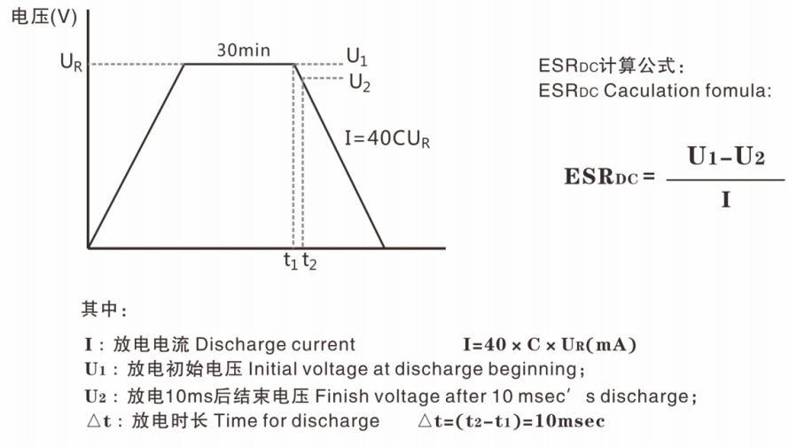
IEC ESRDC 测试方法:
IEC ESRDC Test method:
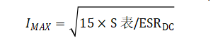
- 最大工作电流:15℃温升时的最大工作电流
Maximum operating current: the maximum current when temperature rised 15℃
- 最大峰值电流:1秒钟放电至1/2UR的最大放电电流
Maximum peak current: the maximum current which the capacitor discharges from UR to1/2Unin 1 second.
IMAX=0.5UR/(RDC+1/C)
- 漏电流:25℃下恒压72小时后的泄漏电流
Leakage current: the current after 72 hours constant voltage load in 25℃
- 最大储存能量Maximum storage energy:
E=0.5CUR²
- 功率密度Power density:
Pd=(0.12*UR²/ESRDC)/mass
- 能量密度Energy density
Ed=(0.5CUR²)/(3600*mass)
Supercapacitor Calculation Formulas (Download Related Documents)
Customers can provide information about their usage conditions using the application information form below. By filling out the corresponding usage conditions in the table and submitting the application form to us via email or contact, we will be able to better understand your conditions and recommend products that are more suitable for your needs.
- Customer Needs Assessment Form
- Super Cap Module AGV Solution Inquiry Form
- LIC Usage Condition Inquiry Form
Please complete the inquiry form in detail, as it greatly assists us in recommending the appropriate product models for your needs.
If you have any questions, please contact zfw@cda-cap.tw.
Button Cell Battery is widely used in a variety of small electronic devices and precision instruments due to its small size, moderate capacity and easy installation. The following is a classification of its main uses:
1. Daily electronic devices
Watches: traditional quartz watches, smart watches (such as some models use CR2032 batteries).
Calculators: small portable calculators.
Remote controls: car key remote controls (such as CR2025), home appliance remote controls.
Electronic toys: mini electronic pets, LED light-emitting toys.
Portable lamps: LED flashlights, decorative lights.
2. Medical and health equipment
Hearing aids: commonly used zinc-air batteries (such as models PR41, PR44).
Glucose meter: some models are powered by button batteries.
Thermometer: electronic thermometer, infrared thermometer.
Pacemaker (some early models): requires medical-grade high-stability batteries.
3. Computers and electronic products
Motherboard CMOS battery: used to save BIOS settings (such as CR2032).
Electronic dictionaries, portable game consoles (such as early Game Boy cartridge archive batteries).
Smart cards: such as some dongles, access cards.
4. Industrial and professional equipment
Sensors: temperature and humidity sensors, fire alarms.
Electronic tags: RFID tags, Bluetooth trackers (such as Tile).
Precision instruments: measuring instruments, laboratory equipment.
Cameras: metering systems of some traditional film cameras.
5. Other uses
Small electronic gifts: music greeting cards, electronic candles.
Automotive electronics: tire pressure monitoring sensors (TPMS), keychain locators.
Wearable devices: fitness trackers, smart rings.
Fill in the customer’s use condition application information form:
Customers can fill in the corresponding use conditions according to the table below and submit the application information form by email or contact us, so that we will understand your conditions faster and recommend more suitable products for you
• Battery selection condition inquiry form
*Please fill in the inquiry form in detail, which is very helpful for us to recommend the model of the appropriate product for you faster.
If you have any questions, please contact zfw@cda-cap.tw.
**Safety precautions**
Risk of swallowing: Children may swallow it by mistake, so it needs to be stored properly.
Leakage problem: The battery should be removed when not in use for a long time to avoid corrosion of the device.
Environmental treatment: Contains heavy metals and needs to be recycled as hazardous waste.
Although button batteries are small, they are an indispensable energy source in modern electronic devices. When choosing, you need to pay attention to the model, voltage and applicable scenarios.