 English
 Chinese
Abstract:This article presents the factors influencing the lifespan of EDLC, including temperature, applied voltage, and voltage balancing. It explains the impact of high temperature on the lifespan of EDLC and the underlying reasons. The article analyzes the actual lifespan and temperature difference leading to a halved lifespan for different packaging forms under high-temperature conditions. Additionally, it provides insight into the relative relationship between operating voltage and lifespan. Furthermore, the article examines the balancing effects of different forms of individual cell voltages.
EDLC offer many advantages, such as high energy density, extended lifespan (up to 10 years at room temperature, surpassing traditional batteries), and an exceptionally long charge-discharge cycle life (between 500,000 to 1 million cycles, higher than batteries). These merits have led to the widespread adoption of EDLC across various domains. However, the practical usage data might deviate notably from the values provided in datasheets.
Especially when EDLC are connected in series to form a capacitor module, this configuration can accelerate the degradation of individual capacitor capacities, subsequently shortening the lifespan of the EDLC module. Thus, it is crucial to comprehend the factors influencing the lifespan of EDLC during actual applications and to take measures to mitigate these factors.
The primary factors influencing EDLC include: high-temperature environments, applied voltage, and the voltage balancing characteristics of equalization circuits.
1.Impact of High-Temperature Environments on EDLC Lifespan
Firstly, the nominal lifespan of EDLC as stated in datasheets is typically 10 years at room temperature. However, if we apply the “10-degree rule,” which is a relationship between temperature and lifespan for electrolytic capacitors, we can extrapolate that at the highest operating temperature (65°C), the lifespan would be approximately 5,475 hours, equivalent to around 7.6 months or 228 days.
However, in reality, the high-temperature lifespan of EDLC is significantly shorter than the extrapolated results. Therefore, it’s imperative to analyze the underlying causes. Upon analyzing datasheets, it becomes evident that different manufacturers of EDLC provide varying high-temperature lifespans. For instance, while one manufacturer might indicate a high-temperature lifespan of 1500 hours, another manufacturer might specify 1000 hours.
The discrepancies in high-temperature lifespans stem from differences in manufacturing standards and packaging forms. Figure 1 illustrates the diverse packaging forms among different EDLC manufacturers.
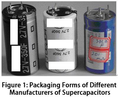
In the figure, “Left 1” and “Left 2” represent packaging forms for standard electrolytic capacitors, which are relatively cost-effective. The high-temperature lifespan for this packaging approach is approximately 1000 hours. On the other hand, the high-temperature lifespan for the packaging form depicted on the right is 1500 hours.
If the nominal lifespan at room temperature is consistently 10 years, then the room temperature to high-temperature lifespan ratio for the standard electrolytic capacitor packaging forms is 87.6. This corresponds to a temperature difference (ΔT) at which the lifespan is halved, calculated as:
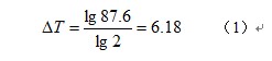
Equation (1) indicates that for EDLC using standard electrolytic capacitor packaging forms, the temperature difference at which the lifespan is halved is approximately 6.2°C. Consequently, when considering an ambient temperature of 50°C, the corresponding temperature difference becomes 15°C. This is 2.43 times the 6.18°C, which means an additional factor of 2 raised to the power of 1.43. This corresponds to an actual lifespan of approximately:
![]()
This results in approximately 2694 hours of lifespan, rather than the approximately 11000 hours estimated using the 10-degree rule.
For the packaging form furthest to the right in the figure, the room temperature to high-temperature lifespan ratio is 58.4. This corresponds to a temperature difference (ΔT) at which the lifespan is halved of:
![]()
Equation (3) demonstrates that for EDLC using the packaging form depicted in the far-right of Figure 1, the temperature difference at which the lifespan is halved is approximately 5.87°C. Thus, when considering an ambient temperature of 50°C, the corresponding temperature difference becomes 15°C. This is 2.56 times the 5.87°C, which equates to an additional factor of 2 raised to the power of 1.56. This corresponds to an actual lifespan of approximately:
![]()
This corresponds to approximately 4433.8 hours. Clearly, the result obtained from Equation (4) is 1.64 times that of Equation (2). Thus, under the conditions of an ambient temperature of 50°C, in order to achieve an economic balance point, the price of EDLC using the standard electrolytic capacitor packaging form needs to be 61% of the price of the packaging form shown in Figure 1 on the far left. When selecting the brand and specifications of EDLC, it’s important to consider their high-temperature lifespan.
2. Impact of Applied Voltage on EDLC Lifespan
Unlike aluminum electrolytic capacitors, the lifespan of EDLC when subjected to applied voltage is shorter than when no voltage is applied. The relationship between applied voltage and EDLC lifespan is depicted in Figure 2 below the rated voltage.
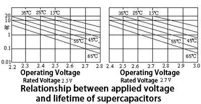
Clearly, applying a voltage below the rated voltage extends the lifespan of the EDLC, while applying a voltage above the rated voltage shortens it, and the rate of lifespan reduction can even be faster.
3. Impact of Voltage Balancing Circuit’s Equalization Characteristics on EDLC Lifespan
Since the rated voltage of EDLC is quite low, practical applications often involve connecting multiple, sometimes dozens or even hundreds of EDLC in series to form a EDLC module. The issue here is that variations in capacitance and leakage current among individual EDLC can lead to differences in the actual terminal voltages of these components within the EDLC module. Over time, these differences tend to increase. Consequently, voltage balancing measures are necessary when using EDLC in series.
The simplest voltage balancing measure involves connecting resistors across the terminals of each EDLC, as shown in Figure 3.
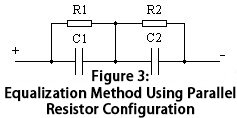
While this voltage balancing method is straightforward, its effectiveness is limited, and it also incurs significant losses. For instance, paralleling a 100Ω resistor across a terminal voltage of 2.5V results in a current of 25mA and a power loss of 0.0625W.
The challenge lies in the fact that even with a charging current of 1A, the balancing current of 25mA has minimal voltage division effect. This is because the balancing current on the balancing resistor is determined by the voltage difference across each balancing resistor. If this voltage difference is only 0.2V, the balancing current will also be merely 2mA, which is 1/500th of the charging current.
Consequently, this type of voltage balancing method often lacks effective voltage equalization. As a result, during the charging process, the capacitance of the EDLC lags behind that of individual EDLC, causing over-voltage in that particular EDLC. This over-voltage shortens its lifespan compared to the others. This is why EDLC modules using resistor-based voltage balancing methods tend to have a shorter lifespan than individual EDLC.
To address this issue, an active voltage balancing circuit is required. The circuit is illustrated in Figure 4.
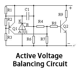
This type of voltage balancing circuit is effectively equivalent to a voltage-stabilizing diode, with the added advantage of excellent temperature stability and high current capacity. It can achieve a balancing current of up to 5A, which is 2000 times that of the circuit in Figure 4!
However, a drawback of the circuit in Figure 4 is that it only operates above a certain clamping voltage, achieving voltage equalization. Below this clamping voltage, it functions as a static current source, not contributing to the voltage equalization process throughout the charging cycle.
A more effective voltage balancing approach is dynamic voltage balancing, as depicted in Figure 5.

This dynamic equalization process can commence when the terminal voltage of an individual EDLC reaches 1.2V. Consequently, effective voltage balancing can be achieved during the charging process from 1.2V to 2.5V or 2.7V.
Conclusion
The lifespan of EDLC primarily depends on the operating temperature. Additionally, the higher the operating voltage, the shorter the lifespan of EDLC. Imbalances in the terminal voltages of individual components within a EDLC module also impact their lifespan. Employing effective voltage balancing can significantly mitigate these effects by equalizing the terminal voltages of EDLC.